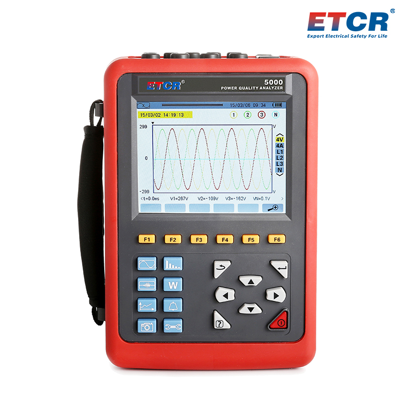


| Measurement Specifications | Measurement Range | Display Solution | Max. Error Within The Reference Range |
| Frequency | 40Hz~70Hz | 0.01Hz | ±(0.03)Hz |
| True Effective Value Of Phase Voltage | 1.0V~1000V | Min. Solution 0.1V | ±(0.5%rdg+5dgt) |
| True Effective Value Of Line Voltage | 1.0V~2000V | Min. Solution 0.1V | ±(0.5%rdg+5dgt) |
| DC Voltage | 1.0V~1000V | Min. Solution 0.1V | ±(1.0%rdg+5dgt) |
| True Effective Value Of Current | 10mA~6000A | Min. Solution 1mA | ±(0.5%rdg+2dgt) |
| Peak phase voltage | 1.0V~1414V | Min. Solution 0.1V | ±(1.0%rdg+5dgt) |
| Peak line voltage | 1.0V~2828V | Min. Solution 0.1V | ±(1.0%rdg+5dgt) |
| Peak Current Value | 10mA~6000A | Min. Solution 1mA | ±(1.0%rdg+5dgt) |
| Peak Factor | 1.00~3.99 | 0.01 | ±(1%rdg+2dgt) |
| 4.00~9.99 | 0.01 | ±(5%rdg+2dgt) | |
| Active Factor | 0.000W~9999.9kW | Min. Solution 0.001W | ±(1%rdg+3dgt); Cosφ≥0.8 |
| ±(1.5%rdg+10dgt);0.2≤Cosφ<0.8 | |||
| Reactive Power Inductive & Capacitive | 0.000VAR~9999.9kVAR | Min. Solution 0.001VAR | ±(1%rdg+3dgt);Sinφ≥0.5 |
| ±(1.5%rdg+10dgt); 0.2≤Sinφ<0.5 | |||
| Apparent Power | 0.000VA~9999.9kVA | Min. Solution 0.001VA | ±(1%rdg+3dgt) |
| Power Factor | -1.000~1.000 | 0.001 | ±(1.5%rdg+3dgt);Cosφ≥0.5 |
| ±(1.5%rdg+10dgt);0.2≤Cosφ<0.5 | |||
| Active Electrical Energy | 0.000Wh~9999.9MWh | Min. Solution 0.001Wh | ±(1%rdg+3dgt);osφ≥0.8 |
| ±(1.5%rdg+10dgt);0.2≤Cosφ<0.8 | |||
| Reactive Power Inductive & Capacitive | 0.000VARh~9999.9MVARh | Min. Solution 0.001VARh | ±(1%rdg+3dgt);Sinφ≥0.5 |
| ±(1.5%rdg+10dgt);0.2≤Sinφ<0.5 | |||
| Apparent Electrical Energy | 0.000VAh~9999.9MVAh | Min. Solution 0.001VAh | ±(1%rdg+3dgt) |
| Phase Angle | -179°~180° | 1° | ±(2°) |
| Tanφ(VA≥50VA) | -32.768~32.768 | Min. Solution 0.001 | ±(1%rdg+5dgt) |
| Displacement Power Factor(DPF) | -1.000~1.000 | 0.001 | ±(1%rdg+5dgt) |
| Harmonic Ratio (Vrms>50V) | 0.0 %~99.9 % | 0.1 % | ±(1%rdg+5dgt) |
| Harmonic Angle(Vrms>50V) | -179°~180° | 1° | ±(3°)harmonic 1~25 times |
| ±(10°)harmonic 26~50 times | |||
| Total Harmonic Rate (DF orTHD-F)≤50 | 0.0 %~99.9 % | 0.1 % | ±(1%rdg+5dgt) |
| Distortion Factor (DF or THD-R)≤50 | 0.0 %~99.9 % | 0.1 % | ±(1%rdg+10dgt) |
| Transformer K-factor | 1.00~99.99 | 0.01 | ±(5 %) |
| Three-phase Imbalance | 0.0%~100 % | 0.1 % | ±(1 %) |
| Power Supply | Rechargeable lithium battery pack 9.6V, external battery charger. |
| Display Mode | LCD true-color screen, 640dots×480dots, 5.6 inch, display area 116mm×88mm. |
| Battery Level Indication | The battery symbol 5 cells displays the battery levels. When the battery level is lower, it will shut down automatically after 1 minutes. |
| Working Current | About 490mA, The battery works continuously for about 8 hours at full power. |
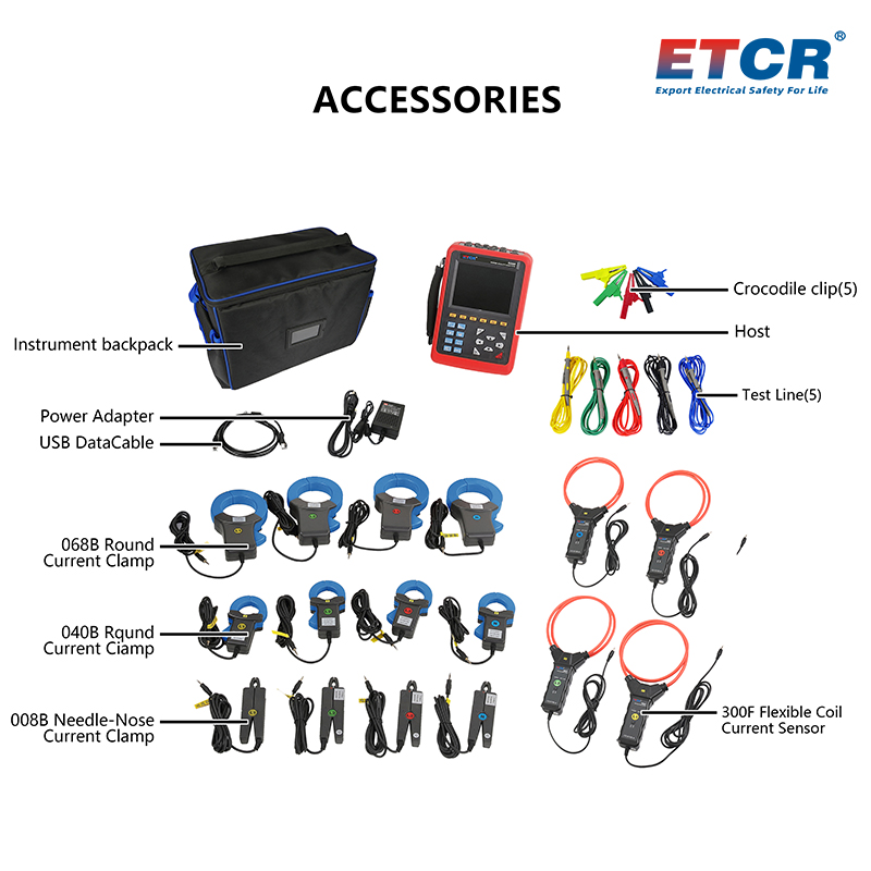
| Clamp Jaw Size | 008B Pointed small current clamp: Φ8mm; (option) 040B Round mouth current clamp: 35mm×40mm; (option) 068B Round mouth current clamp: 68mm×68mm; (option) 300F Flexible coil current sensor: Φ300mm; (option) |
| Number Of Channels | 4 channels of current and voltage |
| Line Voltage | 1.0V~2000V |
| Phase Voltage | 1.0V~1000V |
| Current | 008B Current clamp: 10mA~10.0A; (option) 040B Current clamp: 0.10A~100A; (option) 068B Current clamp: 1.0A~1000A; (option) 300F Flexible coil current sensor: 10A~6000A (option) |
| Frequency | 40Hz~70Hz。 |
| Electricity Quantity Parameters | W, VA, Var, PF, DPF, cosφ, tanφ. |
| Electric Energy Parameters | Wh, Varh, Vah. |
| Harmonic | Yes, 0~50times. |
| Total Harmonic Distortion | Yes, 0~50times, each phase. |
| Number Of Transient Recording Groups | 150 groups. |
| Voltage Flicker | Yes |
| Starting Current Mode | Yes, 100 seconds. |
| Three-phase Imbalance | Yes |
| Record | 300 days (record 20 parameters at the same time, record 1 parameter every 1 minute). |
| Min Max Record Value | Yes, the maximum and minimum values can be measured over a period of time. |
| Alarm | 40 different types of parameters can be selected, and 12,800 sets of alarm logs. |
| Peak Value | Yes |
| Screenshot Capacity | 60 PCS |
| Menu Language | Chinese and English. |
| SD Memory Card | 2G |
| Communication Interface | USB |
| Automatic Shutdown | In the alarm/trend chart recording/transient capture mode (pending or in progress), the instrument will not automatically shut down. |
| In other test mode, no button operation within 15 minutes, automatically shut down after 1 minute prompt. | |
| Backlight Function | Yes, it is suitable for use in dim place and at night. |
| Meter Size | 240mm×170mm×68mm |
| Weight | Host: about 1.6kg (include battery); total weight: about 9.18kg (include package and accessory). |
| Input Impedance | Input impedance of the test voltage: 1MΩ. |
| Withstand Voltage | The sine wave AC voltage of 3700V/50Hz withstand between the instrument circuit and the housing for 1 minute. |
| Insulation | The distance between the instrument circuit and the protective case ≥ 10M Ω. |
| Suitable Safety Standard | IEC 61010 1000V Cat III / 600V CAT IV, IEC61010-031, IEC61326, Pollution Level 2. |
| Working Temperature & Humidity | -10℃~40℃; below 80%RH. |
| Store Temperature & Humidity | -10℃~60℃; below 70%RH. |
| Current Clamp Model | Current Clamp | Current True RMS Value | The Maximum Error Of The True RMS Value Of The Current | Maximum Error Of Phase Angle |
| ETCR 008B CT Size: Ф8mm |
10mA~99mA | ±(1 %rdg + 3dgt) | ±(1.5°),Arms≥20mA | |
| 100mA~10.0A | ±(1 %rdg + 3dgt) | ±(1°) | ||
| ETCR 040B CT Size: Ф40mm |
0.10A~0.99A | ±(1 %rdg + 3dgt) | ±(1.5°) | |
| 1.00A~100A | ±(1 %rdg + 3dgt) | ±(1°) | ||
| ETCR 068B CT Size: Ф68mm |
 |
1.0A~9.9A | ±(2 %rdg + 3dgt) | ±(3°) |
| 10.0A~1000A | ±(2 %rdg + 3dgt) | ±(2°) | ||
| ETCR 300F CT Size: Ф300mm |
 |
10A~99A | ±(1 %rdg + 3dgt) | ±(3°) |
| 100A~6000A | ±(1 %rdg + 3dgt) | ±(2°) |
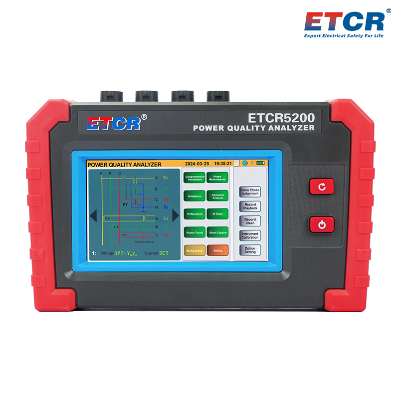
| Product Picture | Product Model Name | Measurement Channel | Current Range | Resistance Range | Harmonic | Transient | Trend Chart | Recorder | Screenshot | Memory Card | USB | Others |
 |
ETCR5000 Power Quality Analyzer | 4 channel | 10mA~6000A | 1.0V~1000V | 0~50 times | Yes | Yes | -- | Yes | SD Card 2G | Yes | |
 |
ETCR5200 Mini Power Quality Analyzer | 4 channel | 10mA~6000A | 1.0V~600V | 2~51 times | Yes | -- | Yes | Yes | TF Card 8G | Yes | True-Color touch screen |

info@etcr.net
(86-757)66860936
(+86)13802922567